PREMIUM HARD TO FIND PC ITEMS:
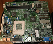
RARE VINTAGE ACER 94138 V16 "VI16" ALI M1451 SOCKET 5 AT MOTHERBOARD WITH MANUAL, CABLES AND DRIVER 3.5" DISC. 48.43801.003MBMX4. . Fully Tested. OEM Surplus.
This is an Acer OEM motherboard made for Siemens Nixdorf S26361-D842 Computer.
** USA Seller ** THE ONLY LISTING ON ! FINAL 5!GOOGLE "S2631-D842" FOR SPECS AND JUMPERS
FLAT USPS PRIORITY Shipping
US-RM1-MBMX4-0000
BUYERS COMMENTS:
Item arrived on time and in great condition. Item works great. Will purchase from the seller again in the future. 10/10! A++++++++ Service & Products! Also - one piece was missing, and took some time to get the seller to send it - but otherwise they rock!RARE VINTAGE ACER 94138 V16 ALI M1451 SOCKET 5 AT MOBO MANUAL DRIVER CABLE MBMX4
SPECS:
SIEMENS NIXDORF INFORMATIONSSYSTEME AG
S26361-D842
ACER, INC.
PI16
Processor
Pentium
Processor Speed
75/90/100MHz
Chip Set
ALI
Max. Onboard DRAM
160MB
Cache
256/512/1024KB
BIOS
Phoenix
Dimensions
330mm x 218mm
I/O Options
Parallel port, serial ports (2), 32-bit PCI slots (4), green PC connector, floppy drive interface, IDE interfaces (2)
NPU Options
None
DRAM CONFIGURATION (CON’T)
Size
Bank 0
Bank 1
Bank 2
64MB
(2) 8M x 36
NONE
NONE
66MB
(2) 4M x 36
(2) 4M x 36
(2) 256K x 36
66MB
(2) 8M x 36
(2) 256K x 36
NONE
68MB
(2) 8M x 36
(2) 256K x 36
(2) 256K x 36
68MB
(2) 8M x 36
(2) 512K x 36
NONE
70MB
(2) 8M x 36
(2) 512K x 36
(2) 256K x 36
72MB
(2) 4M x 36
(2) 4M x 36
(2) 1M x 36
72MB
(2) 8M x 36
(2) 1M x 36
NONE
74MB
(2) 8M x 36
(2) 1M x 36
(2) 256K x 36
80MB
(2) 8M x 36
(2) 1M x 36
(2) 1M x 36
80MB
(2) 8M x 36
(2) 2M x 36
NONE
82MB
(2) 8M x 36
(2) 2M x 36
(2) 256K x 36
88MB
(2) 8M x 36
(2) 2M x 36
(2) 1M x 36
96MB
(2) 4M x 36
(2) 4M x 36
(2) 4M x 36
96MB
(2) 8M x 36
(2) 4M x 36
NONE
98MB
(2) 8M x 36
(2) 4M x 36
(2) 256K x 36
104MB
(2) 8M x 36
(2) 4M x 36
(2) 1M x 36
128MB
(2) 8M x 36
(2) 4M x 36
(2) 4M x 36
128MB
(2) 8M x 36
(2) 8M x 36
NONE
130MB
(2) 8M x 36
(2) 8M x 36
(2) 256K x 36
136MB
(2) 8M x 36
(2) 8M x 36
(2) 1M x 36
160MB
(2) 8M x 36
(2) 8M x 36
(2) 4M x 36
CACHE CONFIGURATION
Size
Bank 0
TAG
256KB
(8) 32K x 8
(1) 8K x 8
512KB
(8) 64K x 8
(1) 16K x 8
1MB
(8) 128K x 8
(1) 32K x 8
CACHE JUMPER CONFIGURATION
Size
JP5
JP6
256KB
pins 1 & 2 closed
pins 1 & 2 closed
512KB
pins 2 & 3 closed
pins 1 & 2 closed
1MB
pins 2 & 3 closed
pins 2 & 3 closed
CPU SPEED CONFIGURATION
Speed
JP10
75MHz
pins 1 & 2, 4 & 5 closed
90MHz
pins 2 & 3, 4 & 5 closed
100MHz
pins 2 & 3, 5 & 6 closed
CPU SPEED CONFIGURATION
Speed
JP13
1.5x
pins 1 & 2 closed
2x
pins 2 & 3 closed
CPU VOLTAGE CONFIGURATION
Voltage
JP16
3.4v
Open
3.55v
Closed
DRQ/DACK CONFIGURATION
DRQ/DACK
JP2
JP3
DRQ3/DACK3
pins 1 & 2 closed
pins 1 & 2 closed
DRQ1/DRQ1
pins 2 & 3 closed
pins 2 & 3 closed
CONNECTIONS
Purpose
Location
Purpose
Location
Serial port 1
CN1
Green PC connector
CN19
Serial port 2
CN2
Power LED & keylock
CN20 pins 1 - 5
Parallel port
CN3
Speaker
CN20 pins 7 - 10
Floppy drive interface
CN4
Green PC LED
CN20 pins 12 - 13
IDE interface 1
CN5
Turbo switch
CN20 pins 15 - 17
IDE interface 2
CN6
Reset switch
CN20 pins 19 - 20
Chassis fan power
CN7
32-bit PCI slots
PC1 - PC4
IDE interface LED
CN17
USER CONFIGURABLE SETTINGS
Function
Jumper
Position
»
On board I/O enabled
JP1
pins 1 & 2 closed
On board I/O disabled
JP1
pins 2 & 3 closed
»
IDE interface enabled
JP4
pins 1 & 2 closed
IDE interface disabled
JP4
pins 2 & 3 closed
»
BIOS type select Flash BIOS
JP12
pins 1 & 2 closed
BIOS type select EPROM
JP12
pins 2 & 3 closed
»
CMOS memory normal operation
JP14
pins 2 & 3 closed
CMOS memory clear
JP14
pins 1 & 2 closed
DRAM CONFIGURATIO


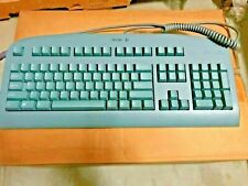
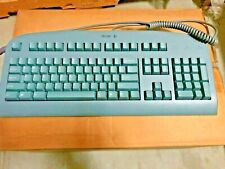
![Vintage Acer KB-123 Keyboard w/ SKCM Blue Alps and Chinese Keycaps [VERY RARE] picture](/store/item/img/g/au8AAOSwz7hl62Al/s-l225/Vintage-Acer-KB-123-Keyboard-w-SKCM-Blue-Alps-and-.jpg)