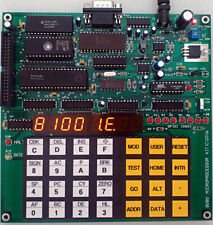
The 8080 microcomputer is three chips system with 8080 CPU, 8224 Oscillator and 8228 bus controller. I used the same platform of my design for microprocessor trainer kit. The board is square PCB with approx. 170mm x 170mm dimensions. The 8080 CPU needs three power supplies, +5V, +12V and -5V. The old day design simply uses linear power supply with multiple turns of a low frequency transformer. However I got the idea to use switching regulators to provide +12V and -5V. For +5V, I used LM2940 low dropout linear regulator. For +12V, I used DC-to-DC converter MC34063. And for -5V I used Intersil 7660. These voltage regulators are placed on the PCB, so the DC input will need only single jack. The kit can be powered with AC adapter +7.5VDC.
Hardware features:
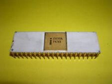
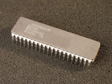
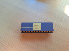
- CPU: 8080 Microprocessor, 2.048MHz (18.432MHz/9)
- Oscillator: 8224
- Bus controller: 8228 with RST 7 strobing for interrupt vector
- Memory: 32kB RAM, 32kB EPROM
- Memory and I/O Decoder chip: Programmable Logic Device GAL16V8D
- Display: high brightness 6-digit 7-segment LED
- Keyboard: 28 keys
- RS232 port: software controlled UART 2400 bit/s 8n1
- Debugging LED: 8-bit GPIO1 LED at location 00H
- Tick: 10ms tick produced by 89C2051 for time trigger experiment
- Text LCD interface: direct CPU bus interface text LCD
- Brownout reset: KIA7042 reset chip for power brownout reset
- HALT and INTE bit indicator LEDs.
- +12V and -5V power supply: MC34063 DC-to-DC converter and Intersil ICL7660.
- Power consumption: 500mA @7.5V AC adapter
- Expansion header: 40-pin header
More technical details: hardware schematic, program examples, please visit
Kit is pre-assembled and tested. No LCD, no AC Adapter.
For DIY kit, same price with free 16x2 LCD.
Free shipping worldwide with tracking.