Commodore 1084 1901 Replacement Power Switch Magnavox 8CM515 Philips CM8833 + Commodore 1084 1901 Replacement Power Switch Magnavox 8CM515 Philips CM8833 +
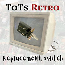
ToTs RETRO
Commodore 1901, 1084, 1084s Philips CM8833, Magnavox 8CM515 (clone 1084) , Atari SC1435, Acorn AKF-17 and more…
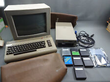
For Use with Commodore 64 64c Commodore 128 128D Atari, Acorn and more….
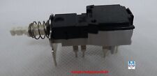
Why pay 25 + plus dollars and $15+ International Shipping. Or why pay anything over $12.99 (not including fixed shipping of $3.99) no matter where you are in the USA. I was looking for a switch to repair my Retro Magnavox 8CM515 so I could use my Vintage Commodore 128 in 80 column mode again….and was outraged by the price gouging going on. So outraged I decided to do something about it. Here is an Alternative Choice you’ve been waiting for! This switch solders on just like your old one and you can use the mount I’ve designed for the switch. Included with the purchase. Your old mount will not fit. . I will also include some heat shrink tubing for you, so that you can keep your solder joints safe.
Fix your Vintage Retro Monitor without having open heart surgery on your wallets.
Specs
TV-5 AC 125v/250v 4A/128A DPST self locking Push Button Switch
Instructions
1a- disconnect power, remove screws and slide case back
1b- slide the board with the switch back and desolder the old switch. (there is a plastic stop under the monitor... push up on the black stop to release the board)
2- remove the old switch
3- mount the new switch with the new custom made mount installed, it will only go on one way
4- connect the screw farthest left of the switch only, the one closest to the tube, this will help you align the switch easily. DO NOT CONNECT THE SECOND SCREW CLOSEST TO YOU
5- place the shrink wrap on the wires moved back a bit so they don’t shrink while you solder do this first for each wire.
6- Solder each wire on in the same order they came off and when completed heat the shrink wrap to make a good seal
7- Gently bend the pins back a bit and towards you. be sure the heat shrink is already applied
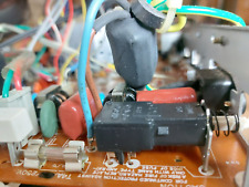
8- pull off the main power switch cap to help you see alignment of the switch as you slide the component back into place
9- these plastics can be a little tricky so take your time I’ve included a photo of what it looks like when you have a decent switch alignment
10- one the board is back in place test the switch for good movement make sure it’s disconnected from power, you can use a wood stick in the bottom bezel that’s a similar diameter or a screwdriver
11- the led likes to come off the main switch , now is a good time to get a little glue if you need to on the PCB board and switch button. Slide the button cap back in place with its spring. You are all ready to go . ENJOY!
Click to edit text Listing and template services provided by inkFrog