DIY Retro IC Clock | Teach yourself to Solder | Vintage 80’s Style RED LED DIY Retro IC Clock | Teach yourself to Solder | Vintage 80’s Style RED LED
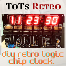
ToTs RETRO
Vintage Style LED Clock
Teach yourself to solder. This is a great Segway into learning how to work on vintage style components and electronics Follow the PCB printed layout and reference pictures on how to put items together properly
DIY Kit List:
PCB board X1
0.56 digital tube 1 bit common negative X6
470 ohm resistor X2
1K resistor X50
2.2K resistor X3
100K Resistor X1
10M resistor X1
1N4148 Diode X4
103 Monolithic Capacitor X3
32.768KHZ crystal X1
30P Porcelain Chip Capacitor X2
25V 100UF Capacitor X1
KF301-2PX1
6*6*5 X2
Power Range: 4.5-6volts
Tech Details…. Good to have ….. but not necessary to build clock. 24-hour digital circuit clock, using CD4518, CD4511, CD4081, CD4013, CD4060 and other chips, the circuit does not contain a microcontroller, so there is no program, hours, minutes and seconds can be calibrated, without alarm function.
This kit mainly consists of a second signal generator, counter, decoding display and time calibration circuit. The second pulse is a 1HZ square wave signal obtained by precise frequency division of a high frequency signal generator, which is more accurate in timekeeping.
The second signal generator consists of CD4060 and CD4013, which generates a square wave signal with a frequency of 1HZ. CD4060 is a 14-level binary frequency divider/oscillator. It consists of a 32768HZ oscillator with external resistors R44, R43, C1, C2 and Y1. After 14 levels of binary frequency divider, the frequency of 2HZ square wave signal is obtained at pin 3. CD4013 contains two independent D flip-flops, take one of the flip-flops through the line configured as a binary counter, binary counting of the input 2HZ square wave signal can be obtained from the second signal. CD4518 is a double-decimal addition counter. With 3 CD4518 for hours, minutes, seconds, hours configured for the 24-binary, minutes and seconds configured for 60-binary. CD4518 counting results in the form of BCD code from pin Q0-Q3 output to the BCD decoder CD4511, CD4511 will be converted to the BCD code corresponding to the display of the corresponding digital tube light segment code, the digital tube to form a digital can be recognized to visually display the current results. Timing results.
Minutes and seconds are counted in 60 decimal, the seconds signal is introduced to the EN terminal of CD4518 through switch S1, and 1 is added to the falling edge of each seconds signal (if the seconds signal is connected to the CLK terminal of CD4518, 1 is added to the rising edge of each seconds signal), and when the counter counts up to 9, Q0-Q3 outputs 1001, i.e., Q3 is 1. As it is a decimal counter, when the next seconds signal arrives, the counter changes from 9 to 0, Q0-Q3 outputs 0000, thus forming a falling edge signal on Q3, this signal is introduced to the ten-digit counter of the second counter, and the ten-digit counter adds 1 to the ten-digit counter after each full count of 10 in the individual counter.When the ten-digit counter value reaches 6, Q0-Q3 outputs 0110, i.e., Q1 and Q2 are both 1 at the same time, and Q1 and Q2 are connected to the counter through an and gate after outputting 1 to the Q1 and Q2 are connected to the reset terminal of the counter through an and gate and output 1, so that the counter counts from 6 to 0 in advance, completing the cycle of 1 hexadecimal counting. The reset signal is also used as the counting signal of the sub-counter, and the sub-counter will be increased by 1 for every full 60 seconds. The sub-counter is also 60-bit, when the sub-counter is full 60, the ten bits of the sub-counter will be reset by a gate, so that the value of the time counter will be increased by 1. When the counter is full 24, the Q0-Q3 of the ten bits will be 0010 and that of the individual bits will be 0100, which will be connected to the counter after Q2 is done with the algorithm, so that the counter can be reset from 6 to 0 in advance. By connecting the Q1 of the tenth bit and the Q2 of the first bit to the reset terminals of the two counters, the hourly counter will return to 0 when the counter reaches the full 24, thus realizing the 24-bit counting.
Click to edit text Listing and template services provided by inkFrog