DESCRIPTION
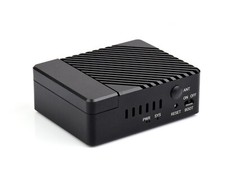
Dual Gigabit Ethernet 5G/4G Base Board Designed For Raspberry Pi Compute Module 4Dual GigE 5G/4G Base For CM4
Suitable For Evaluating The Raspberry Pi CM4 Or Being Integrated Into End Products
Powerful Ethernet Capability, 5G/4G Cellular Support
Communication Module Compatibility
Compatible With Communication Modules With M.2 B KEY Interface
An additional communication module is required to enable 5G/4G/3G/2G cellular network function, SOCKETsuitable for all variants of Compute Module 4NETWORKINGDual Gigabit Ethernet RJ45M.2 B KEY, for connecting 5G / 4G moduleNano-SIM card slot, supports standard Nano-SIM card for 5G/4G/3G/2G communicationUSBUSB 3.2 Gen1 × 2PIN HEADERRaspberry Pi 40PIN GPIO headerDISPLAYMIPI DSI port (15pin 1.0mm FPC connector)CAMERAMIPI CSI-2 port × 2 (15pin 1.0mm FPC connector)VIDEOHDMI × 2, supports 4K 30fps outputRTCReal-time clock with battery socket and ability to wake Compute Module 4STORAGEMicroSD card socket for Compute Module 4 Lite (without eMMC) variantsFAN HEADER5V/12V (12V by default), allows speed adjustment and measurementPOWER INPUT5V/2.5ADIMENSIONS99.6 × 87.0mmWhat's The DifferencesCM4 BASE BOARDINTERFACE COUNT AND SPECIFICATIONSPOEGIGABIT
ETH40PIN
HEADERPOWER
INPUTFEATURES
NANO A√2.0×1×15VCM4 sized
NANO B×1√2.0×1×1×1×15VCM4 sized
NANO C√2.0×1×1×1×15VOnboard Camera
DUINOM.2 M2.0×1×1×15VArduino compatible
MINI BASE A×1√M.2 M2.0×4×1×2×25V5Vmini size
MINI BASE B×1√M.2 M2.0×4×1×2×2√5V5Vmini size
MINI BASE C×1√M.2 M2.0×2×1×2√5V5VDedicated 40PIN LCD Connector
TOUCH SCREEN×1M.2 M2.0×4×1×15VIPS screen
MINI DUAL GIGABIT×2√2.0×15V SH1.05Vdual ETH
BINOCULAR CAMERA×1√M.2 M2.0×4×25Vdual 8MP
cameras
4CH RS485×12.0×2×1×2×15V7-36Vdual ETH
WIFI6 DUAL ETH×1√M.2 E2.0×3×1×2×2×15/12V7-36VWIFI6 dual ETH
DUAL GIGABIT style="box-sizing: border-box;">IOT DUAL GIGABIT ETH×2√3.0×2×1×2×2√5/12V5V5G/4G support
IOT support
RS232
RS485
ADC
POE BASE style="box-sizing: border-box;">RS485
POE UPS BASE√×1√M.2 M2.0×4×1×2×2√5/12V7-36VUPS
POE style="box-sizing: border-box;">RASPBERRY PI style="box-sizing: border-box;">WIRELESS BASE×1M.2 B /
7-36V5G/4G support
RS485
CAN
rail-mount
5″ TOUCH SCREEN②×1√M.2 M2.0×4×1×2√5/12V5V
7″ ALL-IN-ONE×1M.2 M2.0×4used×1used√5/12V
used7-36Vtouch screen
camera
speakerNOTE① USB 3.0 is equivalent to USB 3.2 Gen1
② There's PoE header only on the Raspberry Pi official IO board without PoE circuit, that means additional PoE module is required for the official IO board to enable PoE feature.
Unless otherwise specified, the PoE feature here stands for integrating 802.3af-compliant PoE circuit (5V/2.5A).Connecting With Compute Module 4
Standard CM4 Socket And Color-Coded Raspberry Pi 40PIN GPIO Header
Suitable For Compute Module 4 Lite/EMMC Series Module
Rich Interfaces
Providing Interfaces Including: ETH/CSI/DSI/RTC/HDMI/Micro SD/USB/M.2 B KEY
Application Example
Suitable For Raspberry Pi Projects Which Require Multi Peripherals, Or Industrial Applications
for reference only, CM4, display, cameras, and fan are NOT included.What's On Board
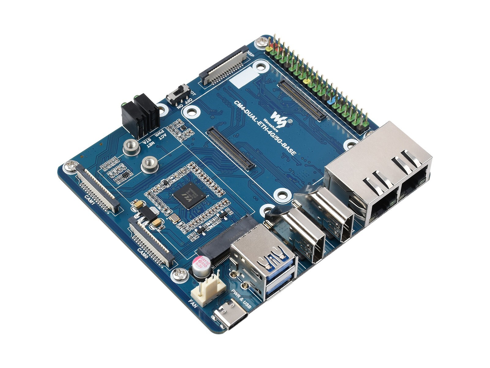
- CM4 socket
suitable for all variants of Compute Module 4 - 40PIN GPIO header
for connecting sorts of HATs - Dual RJ45 Gigabit Ethernet
10/100/1000M compatible
ETHERNET 0: CM4 original ETH
ETHERNET 1: USB extended ETH - HDMI connectors
2x HDMI, supports 4K 30fps output - USB 3.2 ports
2x USB 3.2 Gen1, for connecting sorts of USB devices - PWR & USB
DC power supply or USB programming port - FAN header
for connecting cooling fan, allows speed adjustment and measurement - CAM
2x MIPI CSI camera ports - 4G/5G module status indicator
STA red: module enable indicator
NET green: module operating status indicator - CM4 status indicator
PWR red: Raspberry Pi power indicator
ACT green: Raspberry Pi operating status indicator - BOOT selection
ON: CM4 will be booted from USB-C interface
OFF: CM4 will be booted from eMMC or Micro SD card - DISP
MIPI DSI display port
- M.2 B KEY
supports 4G/5G modules, or other communication modules using USB channel - Nano-SIM card slot
supports standard Nano-SIM card for 5G/4G/3G/2G communication - Micro SD card slot
for connecting a Micro SD card with pre-burnt image (Lite variant ONLY) - RTC battery holder
supports CR2032 button cell - RTC interruption configuration
PI-RUN: CM4 will reboot on RTC interruption
GL-EN: CM4 powerdown on RTC interruption
D4: D4 pin is triggered on RTC interruption (default) - IO-VREF selection
set the CM4 IO logic level as 3.3V (default) or 1.8V - FAN power supply selection
select 12V (default) or 5V power to drive the fan - RTC/FAN I2C bus selection
SDA0/SCL0: I2C-10 is shared with CSI/DSI (default)
GPIO3/2: I2C-1 is shared with 40PIN header - System function configuration
BT_DIS: Bluetooth disabled, for CM4 with antenna variant ONLY
WiFi_DIS: WiFi disabled, for CM4 with antenna variant ONLY
WP_DIS: boot mode switch, ONLY be used when NOT booted from eMMC or SD card - RTL8153
USB Gigabit Ethernet chip
Outline DimensionsPACKAGE CONTENT
Weight:0.076 kg
- CM4-DUAL-ETH-4G-5G-BASE x1
1